Polymeric Monodispersion Microsphere
Principal of LCD and importance of Spacer in LCD application
Basic structure
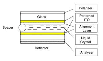
Figure1 shows the general basic structure of liquid crystal display. It is constructed with 2 pieces of glass substrates with sphere or rod shape spacer which determine the cell gap d. Liquid crystal is filled in between two surface alignment layers which determine the orientation of the liquid crystal directors at the boundaries. Transparent Indium Tin Oxide (ITO) layer attached on the glass are used for conduction since the liquid crystal display is electrically driven. The function of the polarizers outside of glass is to modulate polarization of the light that pass through the liquid crystal display so as to realize light switching.

Figure 1 The basic structure of liquid crystal display.
Besides the above stuff, a general liquid crystal display may have some other materials not shown in the above figure such as dopant for liquid crystal, retardation film, light diffuser and backlighting system.
Basic operating principal
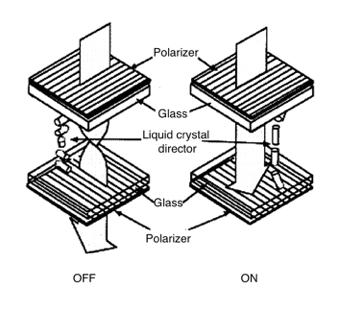
Figure 2 shows an example of operation of the most common Twisted Nematic (TN) liquid crystal display. The twist angle of liquid crystal molecules is 90 ° twisted as boundaries define. The light polarization vector follows strictly to the twist direction and consequently, the structure rotates the polarization plane up to the twist angle. When the light reaches the output analyzer, it totally passes through without loss in principal. Thus the liquid crystal display is operated in bright state.
When a song electric field is applied across the cell, the liquid crystal molecules align along the initial preferred direction but reorient along the electric field perpendicular to the surfaces. Therefore, the light polarization direction almost does not change and, accordingly, the light is blocked when is sees the analyzer. Thus, the liquid crystal display is operated is dark state.

Figure 2 The operation of Twisted Nematic (TN) liquid crystal display
Basic Optics of Liquid Crystal Display
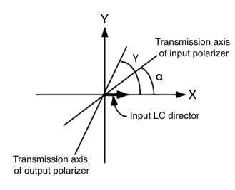
Liquid Crystal Display are electro-optic devices, so it is important that we have a good understanding of optics. Figure 3 shows clearly a simple optical structure of Liquid Crystal Display.

Figure 3 Optics of Liquid Crystal Display
Usually, it is convenient to set input liquid crystal direction to be X axis of the system. The angles of transmission axis of input and out put polarizers are α and γ, respectively. The total twist angle of liquid crystal is φ, which is defined as the angle that liquid crystal is twisted counted from top boundary to the bottom boundary.
Liquid crystal materials are dielectrically anisotropic. On of the consequences of the dielectric anisotropic is optical birefringence. A birefringence material has two refractive indicates: the ordinary index no, and the extraordinary index ne. Birefringence is defined as the difference between the ordinary index and extraordinary index follow:
Δn = ne − no
When light travels in a direction such that it makes angle θ with the optic axis ( the exttraordinary axis ), the effective refractive index ne will be:
ne = sin(π/2 − γ) / sinα
Here, θ = π/2 − γ

